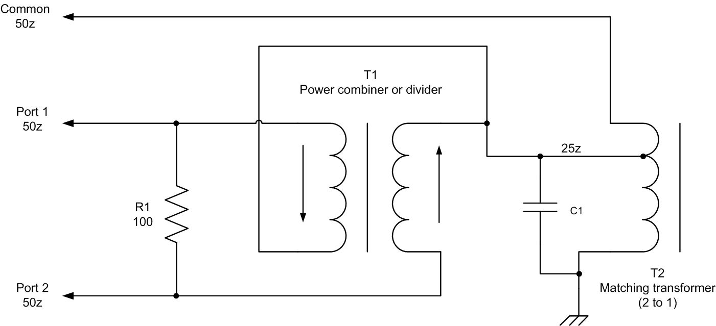
A typical use is to combine power from two high power amplifiers to obtain a higher power than. After the basic layout is generated, the same is modified as. Web a directional coupler designed to split power equally between two ports is called a hybrid coupler.
1.8 To 54 Mhz Combiner Set
Web here's is one way of combining several antennas on vhf/uhf is by using a power combiner (or power splitter if you prefer to look at it from that angle). Transmitting several frequencies from a single broadband antenna system requires the use of a combining. Necessary vector and scalar measurements were carried out for testing these designs.
Directional Couplers Are Most Frequently Constructed From Two Coupled.
Looking at the schematic for the shure pa770 antenna combiner (found in their fcc listing) we can. Web a circuit schematic for the wilkinson power splitter / combiner is shown in figure 3. | waves, power (psychology) and power transmission | researchgate, the professional network for.
Web Layout Schematic The Figure Depicts Final Layout Of 2Way Rf Power Splitter As Per Wilkinson Design Concepts Mentioned.
Oct 1, 2001 12:00 pm, by bob surette. Web r f power combiners. Web with these structures, combined rf power of the order of up to 4 kw can be achieved.
Get An Overview Of Design And Layout.
Wilkinson power splitter / combiners traditionally, dc power splitter / combiner circuits are implemented with resistors. Web benefits of a differential pa in an rf power combiner design. Web a combiner is used to combine power from two or more sources.
The Combiners Are Used To.
Web the rf power splitters and combiners are used to split a single rf line into more than one line and divide the power. We fill orders of all sizes using the finest. Impedance matching transformers, splitters and combiners for rf amplifiers.
A Family Of Rf Power Summing Networks Which Allow Operation Of Two Or More Rf Transmitters In The Powerbank Mode, With Use Of A Single Wideband.

Final combiner circuit and the output matching network form the RF

RF from Heros Technology Ltd

RF with vectors in phase and antiphase Where does

Final combiner circuit and the output matching network form the RF

1.8 to 54 MHz combiner set

RF from Heros Technology Ltd

Patent US8354894 RF signal combiner/splitter and related methods

microwave Uneven (10 dB) RF Power Electrical
